Kingsgate Bridge
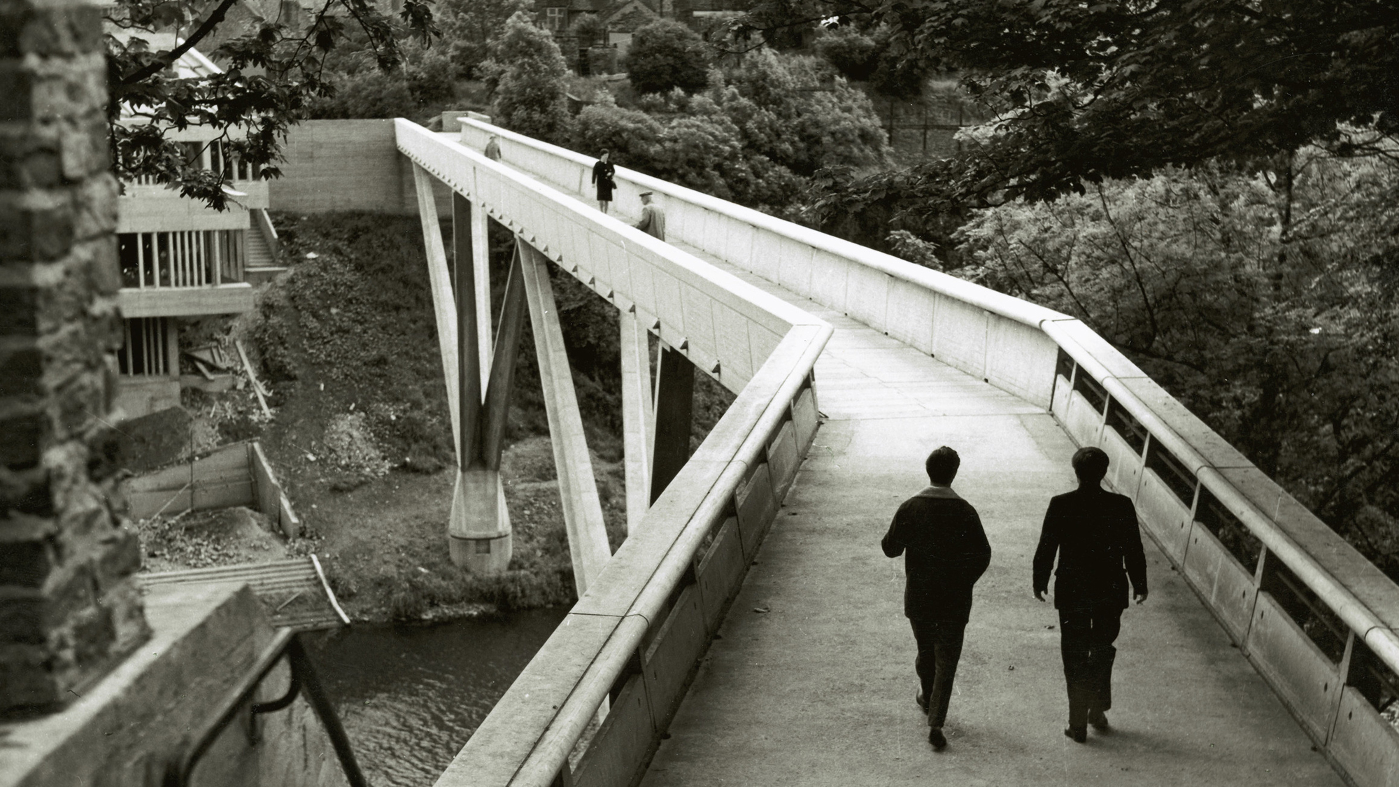
The Kingsgate bridge is a modern reinforced concrete footbridge situated in Durham, England and spans the river Wear. It was designed by Ove Arup, an engineer and architect who founded the firm now known as ARUP Group. This blog post will explore the many facets of this striking bridge structure from the architectural and structural concept to the construction techniques used all the while mixed with notes on the designer, Ove Arup.

Figure 1: The Kingsgate Bridge in Durham, England. Source: https://www.arup.com/projects/kingsgate-footbridge?query=kingsgate
background & architectural concept
At the onset of discussions between Durham University and Ove Arup (and his design team), the concept of a high level bridge spanning from the high topography on each side of the river Wear was immediately suggested by Ove Arup. This was largely due to the opportunity which Ove Arup saw from the high banks and difficult, steep river bank topography. It also presented an opportunity for Ove Arup to continue his view of total design merging architectural and social concepts (connecting the two sides with no need to ascend/descend stairs) and structurally efficient structures (through the lens of pure tensile or compressive structures).
Furthermore, the concept was advanced in a large part due to the method of construction as it was necessary to keep the river open for boating which ruled out the possibility of using scaffolding technique in construction. Ove Arup meticulously designed his concept to eliminate the need for scaffolding accross the river by building the bridge on shore. This was achieved by the design featuring two half-arches which were constructed on each bank of the river and subsequently rotated ninety degrees on their respective supports into position creating the bridge. The meeting point of these two half-arches is marked by a simple bronze expansion joint. The rotation mechanism was designed as two revolving cones with bearings robust enough to allow for the rotation but economic enough to be used only once. The bridge is supported by two slender V-shaped piers.
The bridge itself is a magnificent example of a slender profile which connects to a high shores elegantly highlighting the dramatic topography of it's location and while emphasis the ease of access for Durham's residents. It is also a remarkable example of the symbiosis of engineering and architecture working seamlessly with each other. When finished, Ove Arup considered this bridge his finest work (1) since he considered it to fit his vision of total design. Total design, as mentioned already, is an idea consisting of incorporating all components required in the creation of a structure. In Ove Arup's vision, total design is the incorporation of not just the aesthetics and architecture of a structure but it's structural, mechanical, and construction techniques working in harmony to create the aesthetic, efficient, and optimized structure. This is a inspiring and fulfilling vision for how the different professionals needed to create structures should aspire to colloborate with each other to develop inspiring and innovative designs and structures.
structural concept
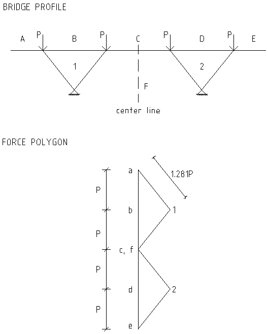
Delving more in-depth into the structural engineering of this elegant structure, it becomes clear that there is also an elegance to the structural concept (see image below). The bridge is a symmetric structural concept mirrored exactly halfway along the length of the bridge. Moreover, the V-shaped truss supports are placed halfway between each abutment and the centerline of the bridge.

Figure 2: Profile of the Kingsgate Bridge in Durham, England. Source: https://www.arup.com/projects/kingsgate-footbridge?query=kingsgate
But what is the importance of this symmetry from a structural perspective? The symmetry of the design allows the structural elements (with exception of the bridge deck) to be designed as pure compression and tension members. Consider a distributed load acting on the bridge deck (i.e. a load combination of dead plus live load) and transforming it to 4 resultant point loads acting on each support at the level of the bridge deck. By only considering 2 point loads on each half-span which act symmetrically about the support at the point of the V-shaped truss, no moment effects will be experienced (hence allowing the V-shaped truss to act in pure compression). It should be noted that the bridge deck should still be designed to act in bending as a beam supported by the 4 arms of the 2 V-shaped support trusses; however, this is not the focus of this article.
To show the forces which would arise in the V-shaped truss support structure, a force polygon is developed as a method to help our understanding of the structural mechanism of this bridge. For this article to not bcome so technical, I will simply refer to the point loads acting on the structure (see previous paragraph) as \(P\) and not calculate a specific value corresponding to a specific load combination. The force polygon for this structural concept of the Kingsgate bridge is shown next.

Figure 3: Force polygon for V-shaped trusses of the Kingsgate Bridge in Durham, England.
As you can see from the force polygon, the magnitude of forces in the V-shaped truss support structure is approximately 1.281 times larger than the applied load in the structural concept. The main idea here with the force polygon is that it allows for structural concept to be evaluated quickly based what size of forces we should expect in the structure before any detailed design or finite element analysis can be performed. It is particularly useful in conceptual design phase of a project or used after the fact when analyzing how structures (which exist all around us in everyday life) behave with regard to loading.
Here it can also be seen that by translating points 1 and 2 in the force polygon horizontally, we can play with the magnitude of forces in the V-shaped truss members (either increasing or decreasing the force). Not only is this useful for structural engineers but it also allows for closer and more effective colloboration between engineers, architects, clients, and contractors where the engineer can show (not just tell) the architect the benefit of say smaller magnitude forces (i.e. smaller structural members) while the architect may prefer a member at a smaller angle (i.e. moving point 1 or 2 in the force polgyon further away from point a, b, etc.). There are often contradictory demands from the various engaged professionals where the force polygon method can be a useful tool to deal with these inherent contradictions in the design process. These contradictions lead directly to the vision of total design which aspires to reconcile these inherent contradictions during the design process and this is to a large extent also Ove Arup's inspiration to pursue the perfect total design method as a way to perserve and highlight the elegance of a design concept.
conclusion
To conclude, the Kingsgate bridge is a striking example of not just architecture and structural engineering working harminously together but also of innovative construction techniques and a masterclass in total design. From this case study, a useful tool in achieving more effective colloboration between engineers and architects (and also others involved in the design process) is the force polygon method as a way of communicating the different demands between say the structural forces and the shape of the structure. In the next post, I will explore and explain more about the force polygon method with specifics on how to use the method and some pitfalls to avoid. I hope that this article has inspired you to see the Kingsgate bridge in Durham, England from a new perspective and be able to see the structures around you in your everyday life differently as well. Until next time, have a great two weeks and goodbye.
references
(1) ARUP Group. A striking example of Ove Arup's bision for 'total design'. https://www.arup.com/projects/kingsgate-footbridge. Accessed on 2019-09-22.