Structural timber floor: Stressed skin panels (SSP)
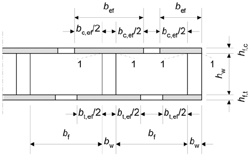
Even though nowadays cross-laminated timber (CLT) products are becoming very popular in the design of tallwood structures especially within the context of sustainability in infrastructure, there is still a use for a older type of structural timber floor system called the stressed skin panel (SSP) system. The next question you are probably asking is what actually is a stressed skin panel floor system. Simply put a SSP timber floor is a system of timber thin-flanged I-beams. Timber thin-flanged I-beams are a type of built-up section where the flanges and the webs are glued together and act as a unit structurally. Typically, a SSP floor system will consist of prefabricated elements containing one full I-beam which are then connected together on-site. Here is an example of what a stressed skin panel is including it's constitutive parts.

The remainder of this post will explore the structural calculations needed to properly ensure the safety, appearance, and comfort of SSP timber floors based on the design philosophy of the Eurocode (EC5). The structural verifications are based on the following 3 areas:
- stress verification -> safety using the ultimate limit state (ULS)
- deflections -> appearance using the serviceability limit state (SLS)
- vibrations -> comfort using serviceability limit state (SLS) or FE analyses
Limit states are the idea that we design based on probability of failure. Usually, the probablistic criteria is the 5th percentile value of the parameters being used to provide, for example, safety. In other words, we utlize the top 5th percentile of the applied loads (using load combinations) and compare with the respect to the bottom 5th percentile of the resistance provided by the structural material. The basis of this is best summarized as over-estimating the load applied on and under-estimating the resistance provided by the structural member.
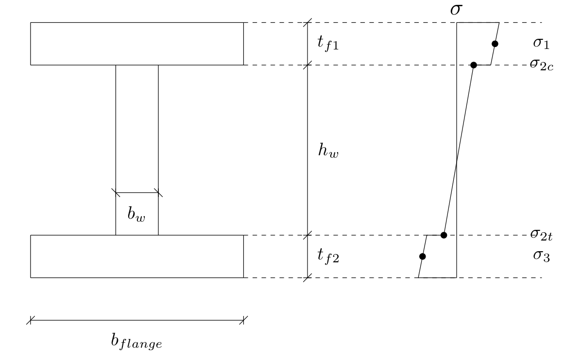
To complete the discussion of these 3 areas, a more detailed drawing of a SSP timber floor system is shown below:

Stresses in ULS
To design a SSP timber floor, the stresses in the ULS condition should be verified as less than the stress resistance provided by the material. Since a SSP timber panel consists of a built-up timber I-beam, only specific locations over the cross-section need to be verified in terms of the stress. From basic structural analysis of beams under bending, there will exist compressive and tensile stresses in the top and bottom flanges of a I-beam (assuming a simply-supported beam), respectively, but in general compressive stresses exist where negative bending moments exist and vice versa. Assuming linear variation of the strain over the cross-section of the I-beam, the stress at the most extreme fibers will be critical in general for rectangular, homogenous material I-beams. The difference, when the I-beam is built-up with various materials, is that the stresses should be checked in the critical locations. For thin-flanged I-beams the stresses which need to be verified are the axial compressive and tensile stresses in the compression and tension flanges, bending compressive and tensile stress in the web, panel shear stress in the web, and rolling shear stress in the glued flange-to-web connection of the built-up panels.

But what exactly is meant by the last stress to verify, rolling shear? Rolling shear is the shear which exists between two surfaces which are glued or mechanically connected. In the case of SSP timber panels, the shear stress in the glued connection between the flanges and the web is the rolling shear which needs to be checked. In terms of EC5, the design of the rolling shear stress is calculated as:
\[ \tau = \frac{VS}{Ib} = \frac{VSE_i}{EI_{tot}b_w} \]
While the design rolling shear stress resistance is determined as the minimum from the material properties of the timber components of the I-beam which are glued together. Specifically, if solid timber is used, then it is sufficient to simply assume that the rolling shear resistance is twice the shear resistance. For the most part, the ULS condition is fairly straightforward to ensure and most timber floors will likely be governed by deflections or vibrations which are discussed in the next sections.
Deflections in SLS
For deflections of SSP panels, both bending and shear deflections need to be accounted for because shear deformations may not be neglected.
\[ u_{inst} = \frac{5qL^4}{384EI} + \frac{6M_d}{5GA} \]
Additionally, not just the instantenous deflection needs to be checked but also the final (creep) deflection should be verified against limits stated within the EC5 or specified by the client. EC5 specifies minimum deflection requirements for timber structural beams are shown below where \(l\) represents the beam span:

Final (creep) deflection is calculated using the \(k_{def}\) factors in the EC5 which is a time-dependent property of the timber material product used. Because the final deflection is related to creep which is a time-dependent property as already mentioned, the deflection due to different categories of load will be different. Therefore, the following equations may be used to calculate the final (creep) deflections:
\[ u_{fin} = u_{fin,G} + u_{fin,Q} \] \[ u_{fin,G} = u_{inst,G} (1 + k_{def}) \] \[ u_{fin,Q} = u_{inst,Q} (1 + \psi_2 k_{def}) \]
As seen here, the calculations for the deflection checks in EC5 are quite simple to perform and reasonable estimates even if the real floor behaviour is complex.
Vibrations using dynamic FEA
Before vibrations can fully be analysed using FE dynamic analyses, a simplified method by hand is utilized to validate the FE model developed. The commercial FE software, Abaqus, is used here to model a SSP timber floor with regard to a vibrational analysis.
First, the guiding principle of EC5 with regard to vibrations is that "the actions which can be reasonably anticipated on a member, component, or structure, do not cause vibrations that can impair the function of the structure or cause unacceptable discomfort to the users". The general requirement is that the fundamental frequency, \(f_1\), should be greater than \(8Hz\) otherwise a special investigation should be performed. This requirement results from the idea that the fundamental frequency of the structure should be significantly different than the frequency of the applied dynamic loading. In residential buildings, the majority of the dynamic loading occurs due to people walking (i.e. footsteps) which have been shown in the literature to dominate in the frequency domain less than \(8Hz\).
EC5 focuses on the concept of springiness of the floor structure. Springiness refers to the perception of vibrations induced by oneself. The way EC5 verifies the vibrational requirements of a floor structure is by calculating:
- the instantenous deflection for a unit point load, and \[ \frac{w_{inst}}{F} \leq a \]
- the velocity response based on, among other parameters, the number of modes under \(40Hz\). \[ v = \frac{4(0.4 + 0.6n_{40})}{mbl + 200} \]
The number of modes below \(40Hz\) can be computed using the following formula in EC5:
\[ n_{40} = \left[ \left( \left( \frac{40}{f_1} \right)^2 - 1 \right) \left( \frac{b}{h} \right)^4 \frac{(EI)_l}{(EI)_b} \right]^{0.25} \]
However, for lightweight floors such as those made from timber it is often advisable to perform a FE analysis to check the effect of vibrations. The main reason as outlined above in the guiding principle of design according to EC5 is that lightweight floors are more likely to exhibit a fundamental period, \(f_1\), similar to the frequency generated by human footsteps than a heavier concrete floor. After validation of a FE model (e.g. by verifying the mid-point static deflection under self-weight with a hand calculation), a dynamic FE analysis can be broken down into 2 general steps:
- a modal analysis, and

- a frequency response analysis.
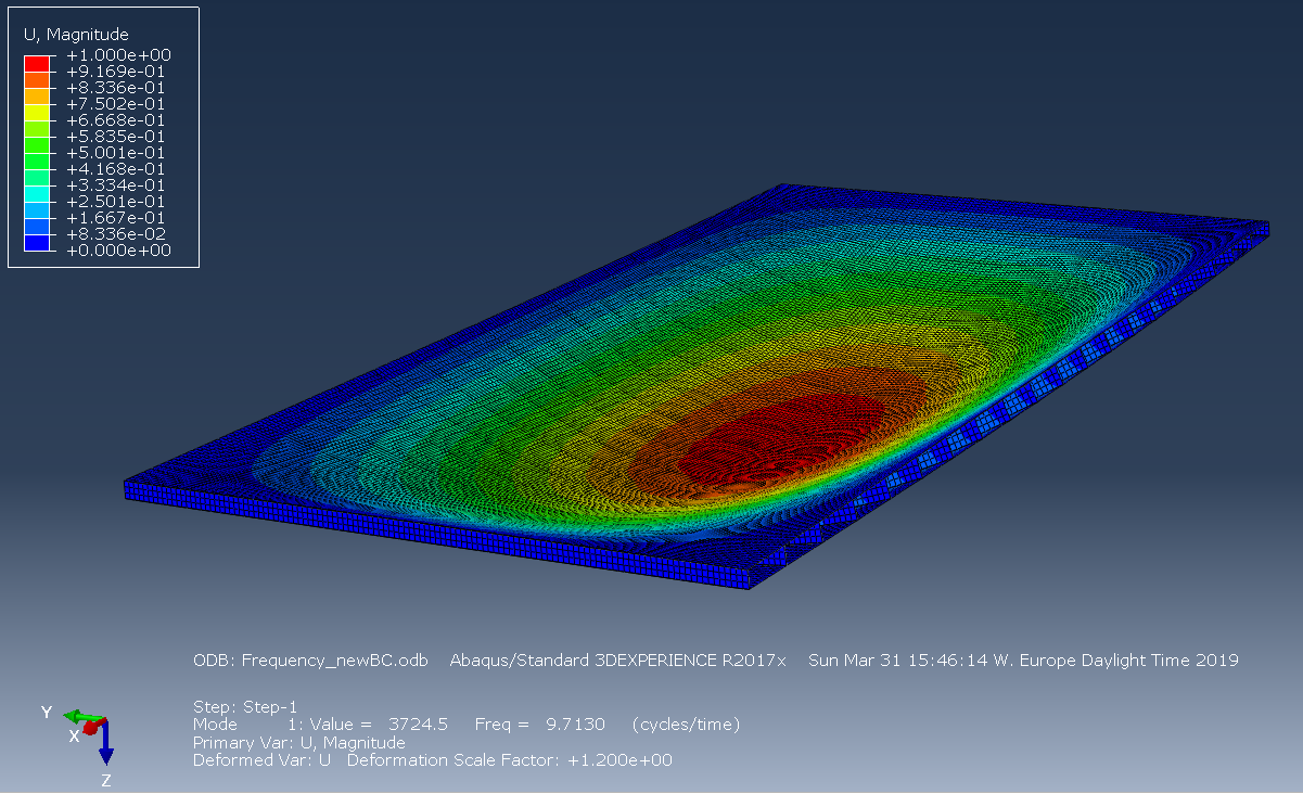
The main difference between a modal and frequency response analyses is that with modal analysis we are only interested in the frequencies at which the system will resonate (i.e. cause structural damage from cyclic deformations) whereas in a frequence response analysis the actual response (deformations) of the system with respect to a certain input frequency (i.e. human footsteps) is determined. Sometimes, a frequency response analysis will be referred to as a dynamic or velocity response analysis which can be generally thought of as similar analyses but the wording generally refers to what is desired as the output from such an analysis. Therefore, when performing a vibrational FE analysis we need to first determine the frequencies at which the floor will resonate (use modal analysis) and then determine the actual response of the system (use frequency response analysis). From performing both types of analyses using Abaqus, the fundamental frequency of the considered SSP timber floor structure as well as the frequency/velocity response of the floor due to a \(100\) Newton concentrated load (applied at \(\frac{3L}{8}\) from the far side of the floor where \(L\) is the length of the floor considered) is shown below.
For those of you who have made it through a longer article, thank you very much. It is much appreciated. In the future look out for future blog posts (coming soon, I promise) on the finite element method. Until then, I hope you enjoyed and learned something for this article.