The "rope effect" behaviour in mass timber doweled connections
Welcome back to my blog! It has been awhile since I have published a article but it was a busy third semester to my masters degree to finish out 2019. I know that this is not an excuse but sometimes other opportunities spring up which you just cannot say no to. I had the opportunity to dig deep into the topics of structural conceptual design (through collaboration with fellow students studying architecture) and structural dynamics. I have already posted an article related to my experience in my structural design course and if you have not read that yet, here is a link to that article. Be sure to stay tuned for upcoming posts on the topics of the finite element method and structural dynamics as well as the topic of my masters thesis: timber connections.
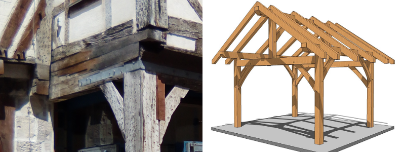
Enough of an introduction, the reason most of you probably clicked on this article is to read about the so-called rope effect. To explain and illustrate what the rope effect is, it is necessary to step back and consider how mass timber structures are generally constructed. Mass timber utilizes in most cases a post and beam construction technique (see below) to carry load although mass timber walls are emerging as a option as well with the popularization of cross-laminated timber (CLT). This is an important distinction between the other major construction type involving timber: light-frame wood construction. To be clear, light-frame wood construction is not the focus of this article since the rope effect is less applicable.

Figure 1: Examples of mass timber post and beam construction. Source: Myself & http://timberframehq.com
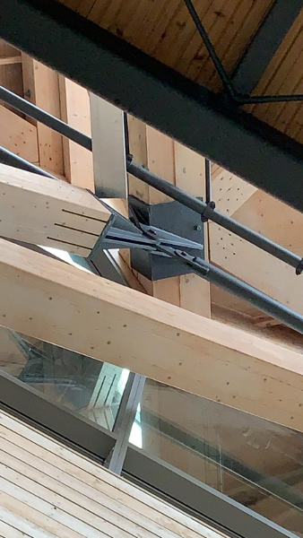
Also, ignoring CLT for our purposes here, in post and beam type of constructions the individual beams and posts (i.e. columns) must be connected to allow for the transfer of load through the structure into the foundation. In steel structures this is often achieved by way of bolted or welded connection details and similarly, mass timber structures are often also connected using steel bolts or more generally with dowels of any relevant material. Typical connectors in timber structures are steel dowel-type fasteners (i.e. bolts, nails, screws, etc.) but traditional carpentry joints using only timber are also common and fiber reinforced polymer connectors are slowly gaining some traction within the design community. Some examples of common connection systems used within mass timber structures are see below.

Figure 2: Common steel dowel and slotted-in steel plate connection in timber structures. Source: Martin Sleiman.
Now armed with this knowledge, the rope effect can be better understood as part of the structural behaviour of these dowel-type connections (i.e. bolts, nails, screws, etc.) when loaded laterally. As a side note to illustrate the concept of ''laterally loaded'', it is useful to consider the analogy of a beam supported by springs from the surrounding timber material. As in any beam-like situation, the main structural behaviour is bending which is exactly the type of behaviour that dowels within dowel-type timber connections experience when loaded laterally. Getting back to designing these types of connections, one typically uses Johansen's theory (or the European Yield Model) to calculate the load-carrying capacity. Johansen's theory divides the task into different categories based on how the connection will fail or put differently what the failure mode is. For a background and historical perspective on Johansen's theory, I suggest to refer back to the original paper published in 1949 by Johansen (cite:Johansen_1949) describing his theory to calculate the ultimate load-carrying capacity. The failure modes according to the European Yield Model consisting of the formation of plastic hinges of the dowel causes bending deformation of the dowel to occur.
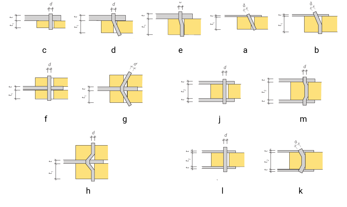
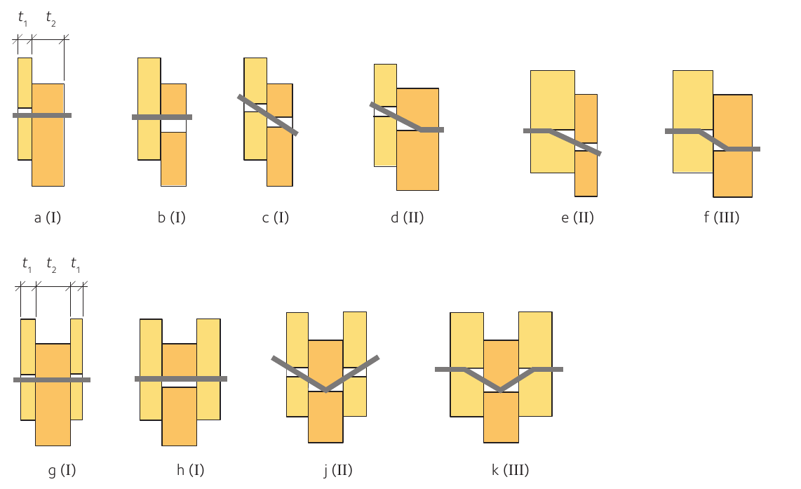
Why you say are bending deformations of the dowel important? The answer is that this change in geometry of the dowel causes the development of axial tensile forces within the dowel evoking the axial withdrawal resistance of the dowel. This then makes it difficult for more bending deformations to occur caused from lateral wood embedment stresses and thus raises the lateral load-carrying capacity of the connection. It can be said that the rope effect increases the load-carrying capacity of laterally loaded connections by evoking the axial withdrawal capacity of the dowels to "assist" the lateral capacity of the connection. This effect is taken into account in the European Yield Model (represented in the current version of Eurocode 5 (cite:EN1995-1-1_2004_EN) and CSA O86 (cite:CSA_2014)) as perhaps expected only for failure modes which are based on dowel yielding. This means that only failure modes which involve bending deformations of the dowels experience the rope effect. From Johansen's Theory (aka European Yield Model), the failure modes which are affected are b, d, e, g, h, k and m and c, d, e, f, j, k for steel-timber and timber-timber connections, respectively. These failure modes are illustrated below for each type of connection.

Figure 3: European yield model failure modes for Steel - Timber doweled connections.

Figure 4: European yield model failure modes for Timber - Timber doweled connections.
Finally, how is the rope effect taken into account in design? Eurocode 5 (cite:EN1995-1-1_2004_EN) accounts for the rope effect by adding the minimum of one quarter of the axial withdrawal resistance, \(F_{ax,Rk}\), and a percentage of the lateral capacity to the shear capacity of the doweled connection. The percentage of the lateral capacity is given by the type of fastener used which for round nails is 15%, for square and grooved nails is 25%, for other types of nails is 50%, for screws is 100%, for bolts is 25%, and for all other dowels is 0%. This is just used as a way to indicate which types of fasteners induce more friction when bent due to lateral load. It should be intuitive to recognize that screws for example will induce much more friction (i.e. due to threads) when bent than smooth dowels will. For more details, on the rope effect take a look at the Eurocode 5 (cite:EN1995-1-1_2004_EN) or CSA O86 (cite:CSA_2014).
That is all, I have to say about the rope effect. It is one of those concepts which once understood makes intuitive sense that it should exist at all; however, before understood it can be difficult to grasp for non-experts. Nonetheless, I hope that by reading this explanation of the rope effect a better picture and understanding emerges.